SYS80 multiplexed display
Study of multiplexing.
Operating principle of the displays in SYSTEM 80 and 80A.
Analysis and detailed datagrams.
Analysis of signals
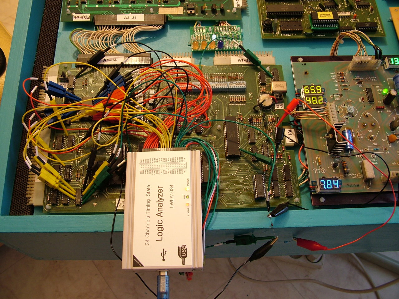
For this study we use a logic analyzer 34 channels connected to the CPU board. To isolate the INT signal of U5 circuit (6532), a 1N4148 diode and resistor were interspersed between the pin of this circuit and the 6502.
Logic analyzer LWLA1014 on the CPU board:
General operation
The multiplexing of the displays uses several groups of signals that allow to manage up to 48 digits. At any given time, only three digits are displayed (which corresponds to groups A, B, C). Strobe signals (D1-D16) command then sequentially in time, other digits (always in groups of three).
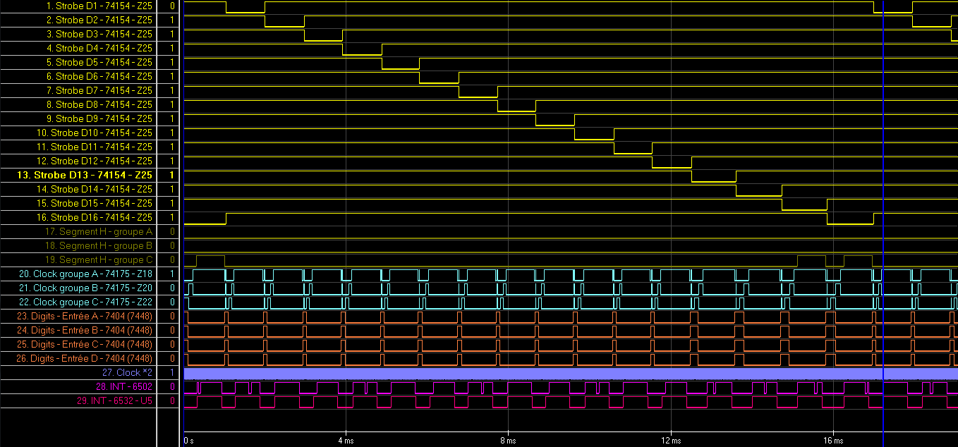
General timeline in SYSTEM 80:
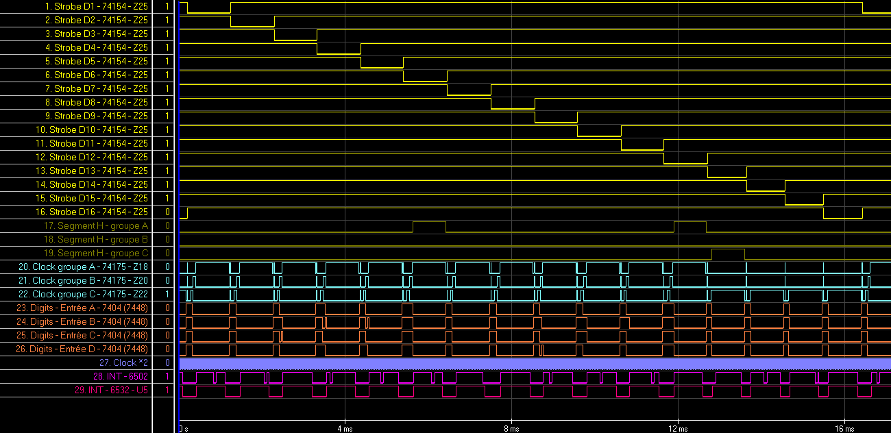
You can see in this timeline, that signals D1-D16 evolve sequentially, their timing being directed by interruptions from U5 timer (6532).
The total length of the sequence is 16.2 ms, a 62 Hz refresh frequency.
Zoom on the piloting of a strobe:
Each strobe remains active during approximately 1 ms, which is also the "average" frequency of the U5 timer interrupts.
The treatment of these interruptions lasts an average of 340 µs, except for the last four strobes (D13...D16) where it is a little shorter, about 230 µs. This is normal, because the groups A and B are not controlled. They are not used in SYSTEM 80 where it needs only small 4-digit displays (only group C is neccessary).
SYSTEM 80, multiplexing is therefore reduced to 40 digits maximum.
Details of an interruption
When a interruption occurs on the U5 timer, the CPU must process the following strobe and present new figures to 74175 latches.
In reality, the duration of treatment interruption is variable because several operations are performed, as for example, the management of the flashing. Despite these variations, the overall time on 16 interruptions is relatively stable.
The U5 timer is reloaded at the end of interruption in order to trigger the next after a fixed interval of 700 µs (time then available for other treatments).
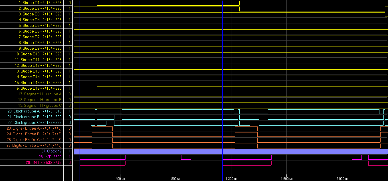
Treatment of an interruption:
As seen on this timeline, these operations are made in several stages. This sequencing is due to the electronic circuit design, which does not allow everything simultaneously. In addition, certain signals are memorized (digits in the 74175) while others are not (H-segments).
- First, then the previous strobe is still active (here D8):
- Resetting the 74175 CLK signals (so inactive)
- Presentation of a given "F" input (to extinguish the displays)
- Simultaneous signal CLK goes 1 on the three 74175 which turns off the display
- The three outputs of H-segments are also reset to zero at this time
- In a second time, it switches to the strobe following (here D9):
- Output of the new value of the strobe and reset signals of 74175 CLK
- Output of the data to display for Group C, then update to 1 the CLK 74175 of group C
- Output of the data to display for Group B, then update to 1 the CLK 74175 of group B
- Output data to display for Group C, then update to 1 the CLK 74175 of the group A
- The three outputs of H-segments are then set simultaneously
In theory, as the three groups are switched off simultaneously, but are then ordered sequentially, their duration is therefore slightly different. Their luminosity is therefore not quite the same, since group C is lit 60 µs before group B, itself lit 60 µs before the group A. In practice, this difference is not noticeable to the eye.
The "H" segments
Gottlieb displays use an additional segment "H" compared to the conventional 7-segment displays. It allows to display a centered "1" instead of "B" and "C" segment usually used.
The management of this segment is entrusted to the CPU which is systematically applied to all figures. The small displays 4-digit doesn't have this segment, an electronic device has been added (74132) to them, in order to regenerate the segments "B" and "C" to form the "1".
The treatment of H-segments is produced as for other digits, during each interruption.
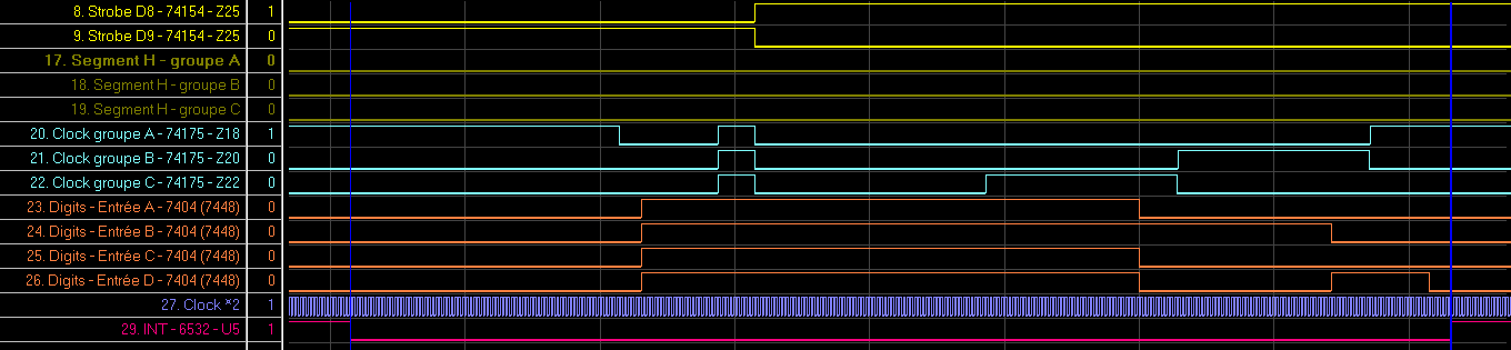
Treatment of H-segments:

In contrast to the stored numbers in the 74175, H-segments are driven directly by the 6532.
- As a first step, H-segments are switched off while the previous strobe is still active.
- In a second time, when it tipped over on the following strobe, three H-segments are activated last.
In this example, the numbers of groups B and C are off, the group A must show a "1". We note that the value presented to the 74175 for group A is an "F" (off) and not a "1".
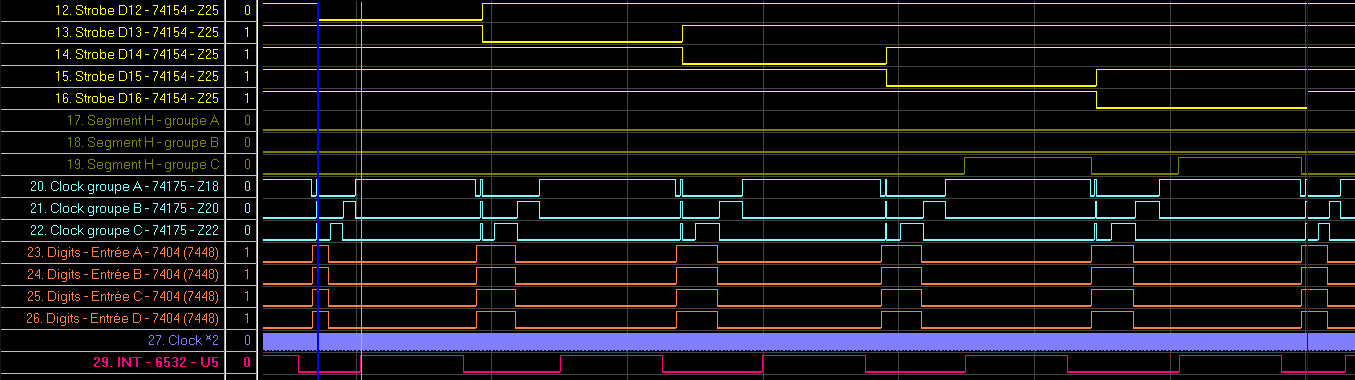
Strobes D13...D16
In contrast to the strobes D1...D12 where the three groups (C, B and A) are used, only the group C is addressed with the D13 strobes...D16.
Treatment for D13...D16:

As a result, the duration of the interruption processing is reduced to 230 µs instead of 340 µs.
Evolutions on SYSTEM 80A
On this system, to display additional digits, the three groups (C, B and A) are also used with strobes D13...D16.
General timeline in SYSTEM 80A:
The average duration of interrupt processing is then 360 µs for D1...D12 and 520 µs for D13...D16.
To account for this increase of processing time, the interval of the timer U5 was reduced to 605 µs. The total length of the sequence is 16 ms, the refresh rate is therefore still of about 62 Hz.
Evolutions on embeded SYSTEM 80A
On our systems 80A, we fixed a bug in the 7 digits display.
General timeline in embeded SYSTEM 80A:

The sequence is similar to that of the 80A, but the average duration of interrupt processing is 350 µs for D1...D12 and 600 µs for D13...D16.
The total length of the sequence is 16.3 ms, the refresh rate is therefore still of about 62 Hz.
The bug fix is at the level of the strobes D13...D16, the corresponding processing sequence is elongated.
Treatment of strobes D13...D16: