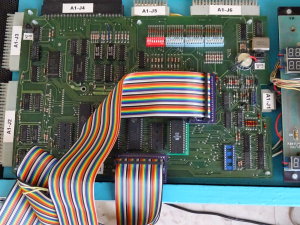
NG Bench test fixture - Probe and components tester

Troubleshooting of electronics boards
Universal bench, for an easy diagnosis
of processor's based systems
All brands of pinballs
(Gottlieb, Bally, ... and many more).
First part of the project
"Bench test fixture NG"
Hardware
The common probe consists of the following:
- An Arduino MEGA 2560
- A LCD 1602 display module (16 x 2) - optionnal
- A "shield" module
- Two ribbons for connecting
- A "DIL40 probe" module
The LCD module used is the DF-Robot, but any will do (the keyboard is not essential). The "shield" and "DIL40 probe" modules are to build but do not present any particular difficulty.
First release of the shield and the probe
In order to validate the concept and save the study of a printed circuit, we first used the original version. This one was indeed, easily and quickly available. We just made a few minor changes, depending on our needs.
But in use, it finally appeared that this shield and this probe was not quite adapted to the intended use. So we decided to design and build our own shield / probe pair: Pinprobe V2.
Connections
These are slightly different from the original project:
- The Arduino must be connected to the PC via the USB cable (though, it does not need external power supply).
- Jumpers on the "probe" connector are not used, do not connect! (No grounding pins 1, 2, 20, 21, 29 or 30).
- The ground will be connected from J13 (on "shield") with a grip or an alligator clip to the adapter to test (it is always easy to find a ground, across a capacitor for example).
- We insert a "lyre" support of 40 or 28 pin between the probe and the circuit. Pin 1 being common to DIL 28/40 (in order to test the CPU to small box like 6503).
- The AUX connector (J14 of the "shield") will be used exclusively input (to avoid accidents).
Examples of connections on 6502 cards (Gottlieb)
The probe comes connect replacing the CPU 6502, or on the TC1 connector. The ground of the probe (connector J13) can be linked to that of the map by a thread. When the probe is ready and that the card is properly fed, the CPU type is displayed on the LCD. If the card is not powered, the probe alert on the LCD.
Attention, even if it can connect two probes on TC1 and 6502, only one can be active at a time. One can also connect the probe to the MA-216 sound cards based on 6502.


Testing SYS80 cards without desoldering the 6502 CPU is possible using the TC1.

In this case, the signals A11 and PHI2 will be injected via wire grip.
Use with other processors (eg 6503)
The probe comes connect replacing the CPU 6503, but by inserting a 28 pin socket. This allows troubleshoot "simple" audio board Gottlieb (6503 + 6530), or the CPU board for cocktail table VALLEY Spectra IV.
Firmware
The probe works of course, after having been programmed with the correct firmware. It is loaded into the Arduino conventionally from USB. The same plug serves as the interface between the API and PC.
The programmed probe can already be tested, without using other software. The API is accessible via USB / serial standard Arduino (115200 baud). We can use the serial monitor the Arduino interface (CTRL + SHIFT + M) to send commands to the probe.
API
The interface provides a number of commands, from simple to complex. The syntax is similar to that used in C, they can beings typed in lowercase or uppercase. All parameters are expressed in hexadecimal and fixed size (1, 2, 4, or 8 digits).
The main control to know is "Help()" that displays the list of all commands and their parameters.
We find there:
- The basic read-write commands common to all systems.
- Other complex commands to test the peripheral components (PIA, TPI, VIA, RIOT and other CIA).
- The calculations of checksums and crc, and controls with specific algorithms (Gottlieb).
- Commands specific to certain systems (Spectra Valley, Gottlieb).
- Some commands also work in 4-bit mode (eg for RAM 5101).
In general, all complex or repetitive treatments were incorporated into the probe. The PC software being relieved of these tasks will be much simpler and easier to write.
Component Tester
This is an additional hardware module on which the probe is connected. It consists mainly of two ZIF supports and several configuration jumpers.
This accessory allows you to thoroughly test complex components such as PIA, RIOT, VIA, CRTC. It also makes RAM, ROM, PAL / GAL and generally all the components that can be found in a pinball machine. It is also an indispensable complement to the probe and can also be operated independently. The probe has a specific built-in menu, which can be navigated using the buttons on the LCD screen.
Grip-wires
The probe is equipped with several test points, easy to use and marked with colors. In order to facilitate their handling, we have used extra soft cable with silicone sheath.
The suitcase
The test bench and the component tester were integrated into a small size metal case. The assembly is thus very well protected and this allows to cleanly store all the cables and tablecloths. Thus finalized, the module has a very professional appearance.
CAVEMAN Interface
In order to test the boards of the CAVEMAN video block, we made an adapter to connect them to the NG test bench. The EPROM and RAM I/O boards can thus be checked directly on the bench.
Software
The software used on PC is describe in the second part of this article.
Distribution
This achievement is not publicly available, in any form whatsoever (free or paid).


